
The role of the isolation switch: in the circuit plays the role of “open” and “closed” circuit, and the above switch than, it has no cut-off ability, that is, can not take the load action, “afraid” arc burning; Can only be used with the above switch, but its special in the structure of “exposure”, can let a person outside can see the circuit is open or broken, maintenance plays the role of “obvious” disconnect point;
Function of disconnecting switch: disconnecting switch is a switch with reliable fracture, and the insulation of disconnecting gap and phase insulation are reliable enough, which can be used to open or close the line with voltage but no load, and also allow to open or disconnect the short no-load line, voltage transformer and no-load transformer with limited capacity.
1.the isolation switch is mainly used to isolate the part of the power distribution device that needs power outage and the live part reliably, to ensure the safety of maintenance work.
2.contact all exposed in the air, has the obvious disconnect point, isolating switch no arcing devices, therefore cannot be used to cut off the load current or short circuit current, otherwise under the effect of high pressure, the disconnect will produce strong arc, and it is hard to out of its own, and may even cause arcing (relative or interphase short circuit), burning equipment, endanger personal safety, This is called a “load pull disconnector” serious accident.
3.The disconnecting switch can also be used for some switching operations to change the operating mode of the system. For example, in a dual bus circuit, an active circuit can be switched from one bus to another bus using a disconnecting switch. At the same time, it can also be used to operate some small current circuits. If the excitation current does not exceed 2A no-load transformer. Capacitive current does not exceed 5A no-load line, some isolation switch with high voltage sensor, can be connected with live display.
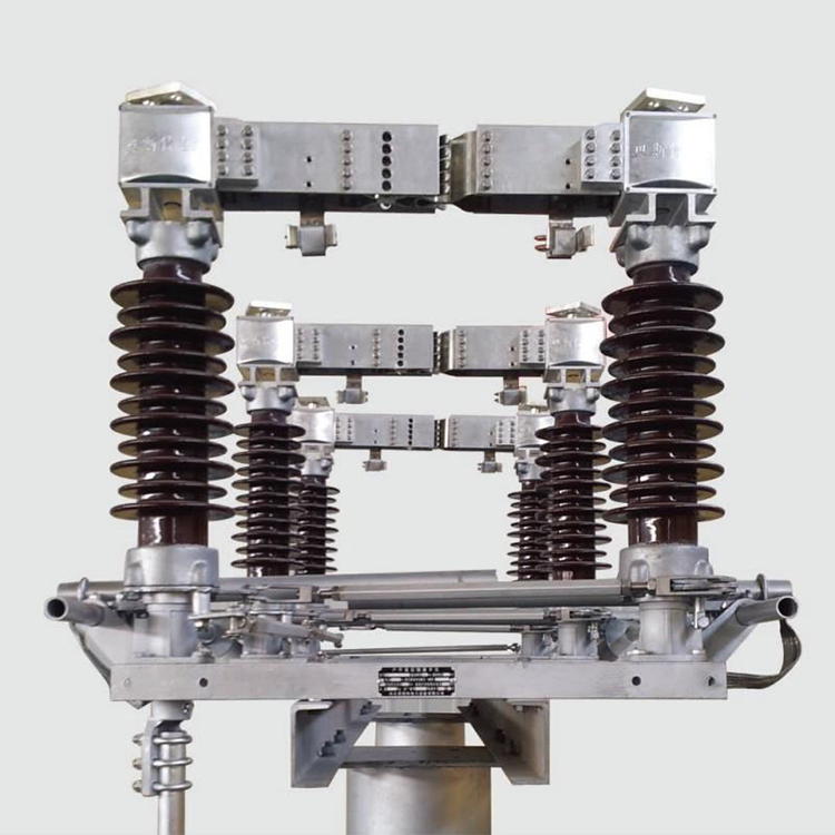
According to the installation site is divided into different types, indoor type and outdoor type, according to the number of insulating pillars, single column, double column and three column type, all voltage levels have optional equipment.
Structure of high voltage isolation switch
1 Conductive part
The static contact is formed by a copper plate bent into a right Angle, and one end of the hole can be connected with the bus through a screw; The other end is shorter, and it is in contact with the moving blade (moving contact) when closing.
Two copper plates form a contact strip, also known as moving contact, which can rotate a certain Angle around the axis and hold the static contact when closing. There is a clamping spring between the two copper plates to adjust the contact pressure between dynamic and static contacts. At the same time, when the current flows in the same direction, the electromotive force between the two copper plates is attracted to each other, which increases the contact pressure and improves the operation reliability. Galvanized steel sheet is installed at both ends of the contact bar called magnetic lock, which ensures that when the short circuit fault current flows through, the magnetic lock magnetized after the mutual attraction force, strengthen the contact pressure, so as to improve the dynamic and thermal stability of the isolation switch.
2 Insulation Part
There are two main kinds of isolation switch insulation, one is to the ground insulation, but the fracture insulation. Insulation to ground is generally composed of post insulators and operating insulators. They usually use solid rod-shaped porcelain insulators, and some use epoxy resin as insulating materials. The insulation of fracture is characterized by obvious gap fracture, and the insulation must be stable and reliable. Usually, air is used as insulation medium, and the insulation level of fracture should be 10%-15% higher than that of ground insulation to ensure that no flashover or breakdown occurs at the fracture.
The static and dynamic contacts are respectively fixed on two sets of supporting porcelain bottles. For those with C in the model, the moving contact is fixed on the casing porcelain bottle. In order to insulate the moving contact from the metal, grounded transmission part, porcelain insulated tie rod insulators are used.
3 Transmission part
There are spindle, arm, tie rod insulator and so on.
4 Base Part
It consists of steel frames. Support porcelain bottle or sleeve porcelain bottle and drive spindle are fixed on the base. The base should be connected to the ground. In short, the isolation switch has a simple structure and no arc extinguishing device. It has an obvious disconnect point when it is in the disconnect position, and its split and close state is very intuitive.
Phase spacing: refers to the distance between the blade of the main switch, because it is to control the phase line, so the distance between is called phase spacing.
Breaking distance: refers to the distance between the knife edge and the corresponding contact plate when the switch is disconnected.
Ground insulation distance: the minimum distance between the switch and the ground.
Pole spacing: the distance between the wiring points on the switch.
Why does the high voltage disconnector specify these parameters?
Because the high voltage can break down the air when it is close to each other, causing the air to ionize and produce a discharge, resulting in a short circuit. I don’t know if you noticed, but most of those parameter names are related to distance. Only in the voltage can not break down the distance, can play a switching role. The insulation distance to the ground is mainly to limit the switch to the ground discharge or discharge, so as not to cause an accident.
Technical performance of high voltage isolation switch
Isolation switch technical data are: rated voltage, rated current, dynamic stable current, thermal stable current; The disconnecting switch has no arcing device, so there is no breaking current data.
Gb1985-2004 “High voltage AC isolating switch and grounding switch” provides the indoor high voltage AC isolating switch corresponding parameters and requirements.
(1) Rated voltage: standard voltage for long-term operation of isolating switch. Rated voltage Take the highest voltage of the equipment, and the rated voltage is 3.6, 7.2, 12, 24, 40.5kV according to the provisions of GB/T11022-1999.
The rated voltage affects the dimensions and insulation level of the disconnecting switch. The higher the rated voltage, the higher the insulation strength, the larger the size, and the larger the distance between phases. The rated voltage is one of the first conditions to be met when selecting disconnecting switches.
(2) Rated current: refers to the current that passes through the disconnecting switch at rated frequency for a long time without damage to the disconnecting switch and the heating of each part does not exceed the maximum allowable heating temperature for a long time. The rated current of the disconnector is selected from the R10 series.
(3) Rated short-time endurance current (usually called thermal stability current) : the effective value of short-time thermal current that the isolation switch can withstand at the closing position under specified use and performance conditions in a specified short time.
(4) Rated peak tolerance current (usually called dynamic stable current)
Peak current that the disconnecting switch can withstand at the closed position under specified conditions of use and performance.
(5) Rated short circuit duration: 0.5s, 1S, 2S, 3s, 4s. The standard value is 2s, and when greater than 2s 4s is usually taken.
As GB/T11022-1999 specifies a higher tolerance test level for isolated breaks than the relative ground insulation, the isolation gap of the isolation switch is usually longer than the relative ground insulation distance.
Large capacity isolation switch, each pole is two blades (moving contact), so because of the electromagnetic force, the contact between the moving contact and the static contact close contact, contact resistance is reduced, in normal and fault current will not occur contact dislocation and welding phenomenon.
Post time: May-07-2022